Overall Design
1. Design Architecture Diagram
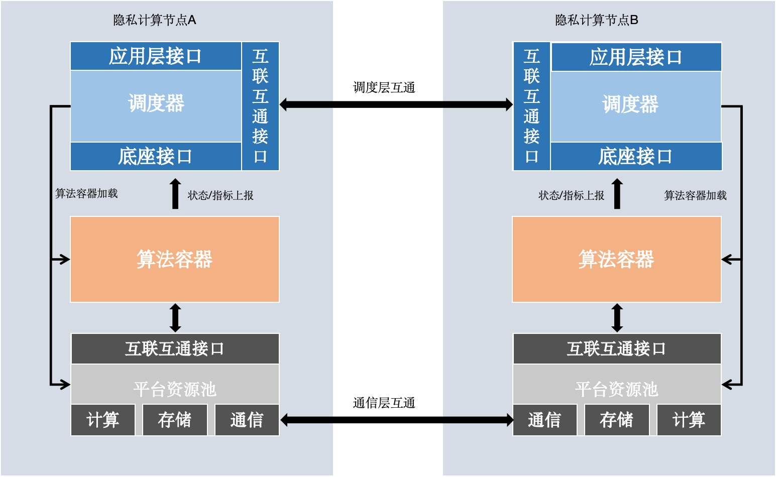 - Application Layer Interface: Used by higher-level components like fate-board, fate-client, etc.
- Interconnect Layer Interface: Divided into Scheduler Interface and Participant Interface. Scheduler Interface receives scheduling commands like create, stop, etc., and sends them to participants. Participant Interface is used by each participant to receive commands like create, run, stop, etc., and execute them.
- Base Interface: Receives status reports from algorithm containers, etc.
- Scheduler: Federated scheduling logic, interprets DSL dependencies, and runs related jobs and tasks.
- Algorithm Container: Environment for algorithm execution. FATE Flow supports running algorithms in local processes or in algorithm containers, with similar execution modes.
- Platform Resource Pool: Abstract computation, communication, storage APIs.
- Application Layer Interface: Used by higher-level components like fate-board, fate-client, etc.
- Interconnect Layer Interface: Divided into Scheduler Interface and Participant Interface. Scheduler Interface receives scheduling commands like create, stop, etc., and sends them to participants. Participant Interface is used by each participant to receive commands like create, run, stop, etc., and execute them.
- Base Interface: Receives status reports from algorithm containers, etc.
- Scheduler: Federated scheduling logic, interprets DSL dependencies, and runs related jobs and tasks.
- Algorithm Container: Environment for algorithm execution. FATE Flow supports running algorithms in local processes or in algorithm containers, with similar execution modes.
- Platform Resource Pool: Abstract computation, communication, storage APIs.
2. Overall Architecture
2.1 FATE Overall Architecture
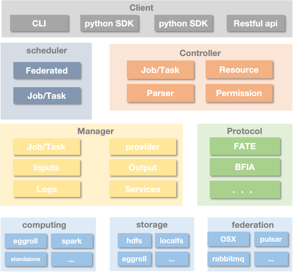
2.2 FATE Flow Functional Architecture
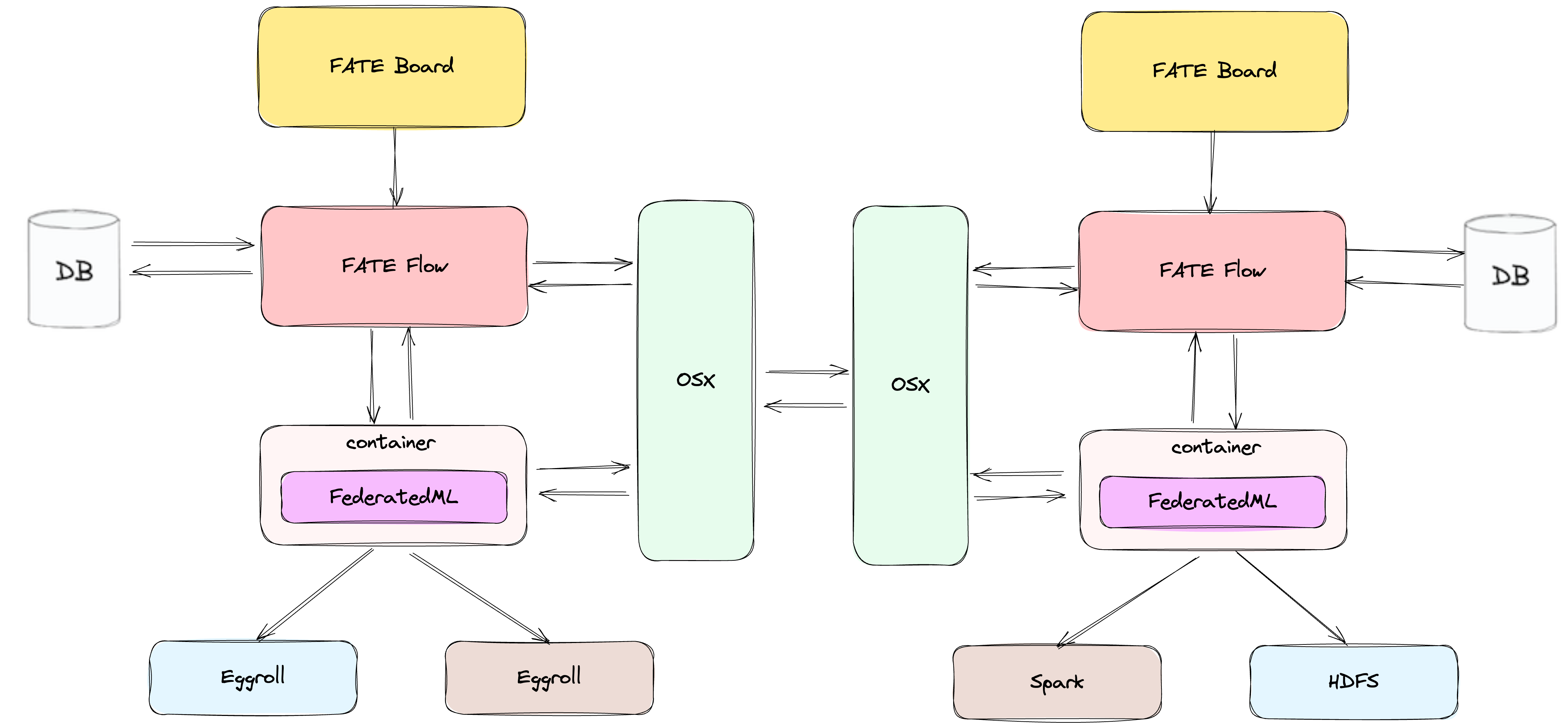
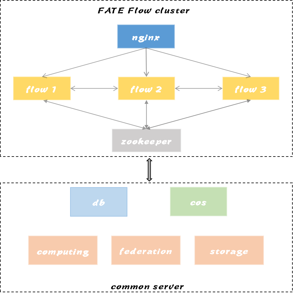
2.3 FATE Flow Cluster Architecture
3. Scheduling Architecture
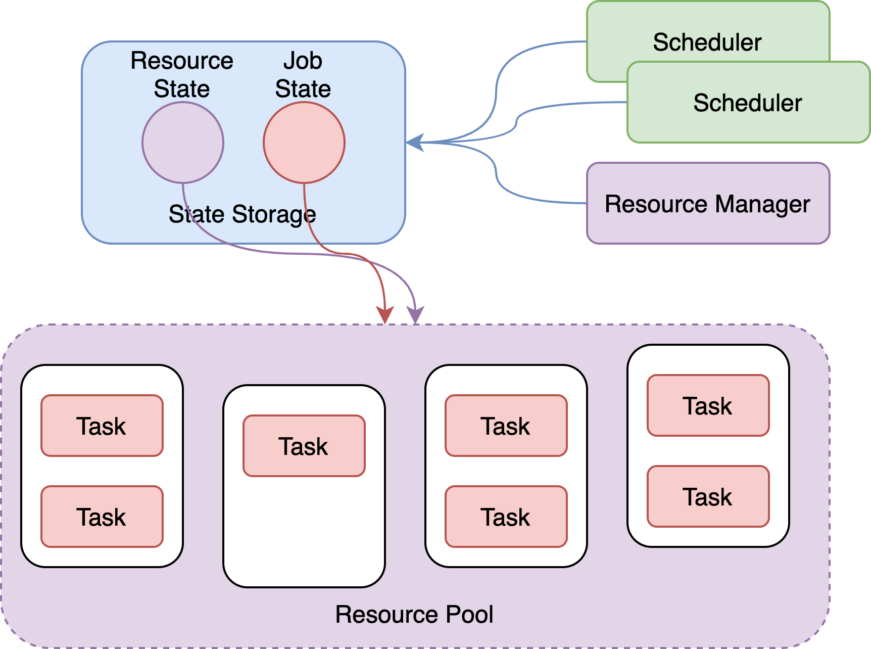
3.1 State-Based Scheduling Architecture
- Separation of states (resources, jobs) and managers (scheduler, resource manager)
- Persistent storage of resource and job states in MySQL, globally shared, providing reliable transactional operations
- Improved high availability and scalability of management services
- Intervention in jobs, supporting actions like restarts, reruns, parallel control, resource isolation, etc.
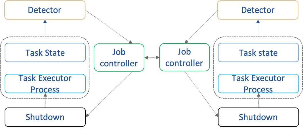
3.2 State-Driven Scheduling
- North-south state reporting/querying
- East-west multi-party task state computation for federated task states
- Upstream and downstream task state computation for job states
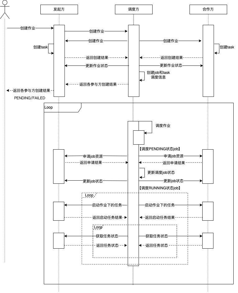
3.2.1 Callback Mode
Scheduler creates jobs and tasks, and each participant actively callbacks the state of jobs or tasks.

3.2.2 Polling Mode
Scheduler not only creates jobs and tasks but also polls the state of jobs or tasks from the participants during the scheduling process.
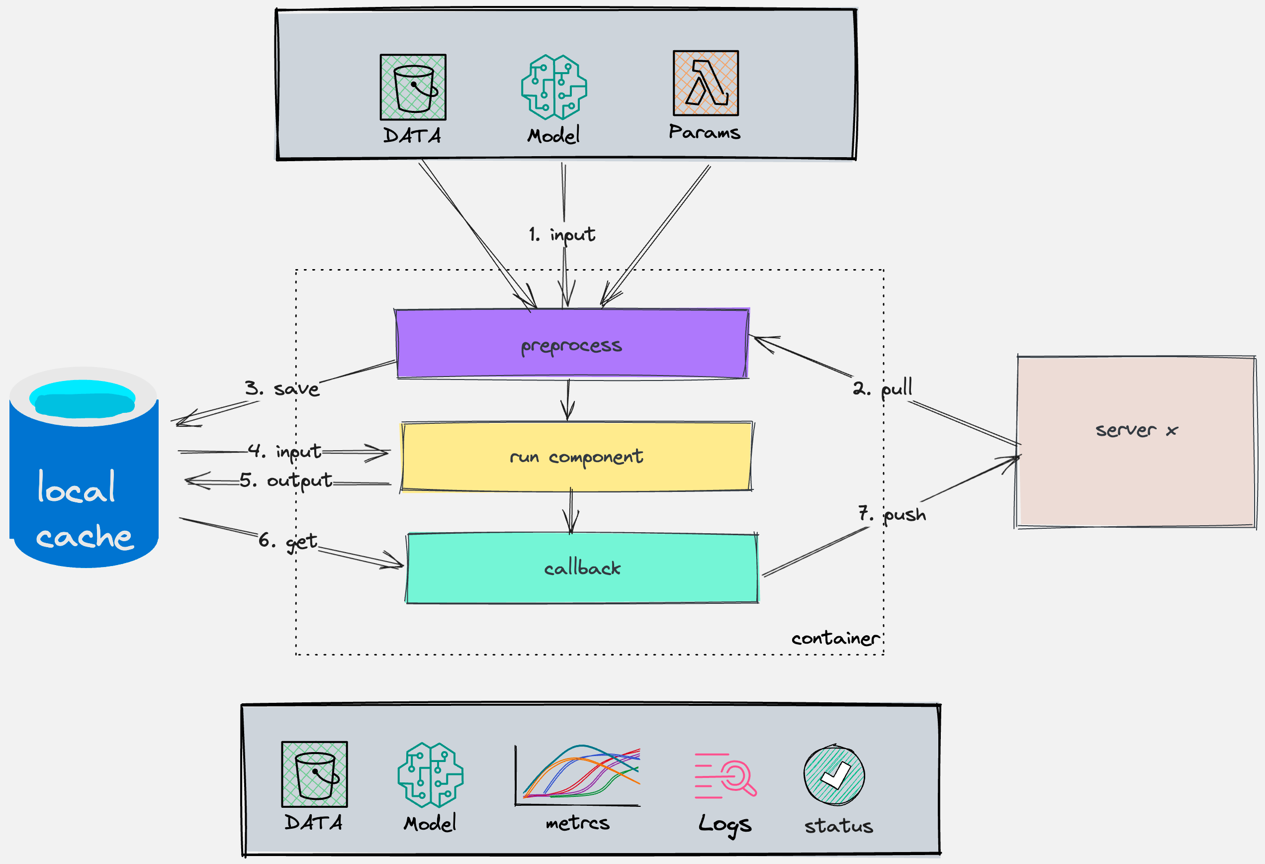
3.4 Algorithm Component Scheduling
- Pre-processing: Handling inputs such as data, models, algorithm parameters
- Component execution: Logic of algorithm components
- Post-processing: Handling outputs of algorithm components
4. Multi-Party Resource Coordination
- Total resource size for each engine is configured via a configuration file, subsequent system integration to be implemented
- The cores within the total resource size represent the number of CPU cores per computing node
- FATEFlow server reads resource size configuration from the configuration file upon startup and registers updates to the database
- Resources are allocated at the Job level, becoming effective upon Job Conf submission
5. Real-time Job Monitoring
- Work process liveness detection
- Job timeout detection
- Resource recovery detection
- Basic engine session timeout detection
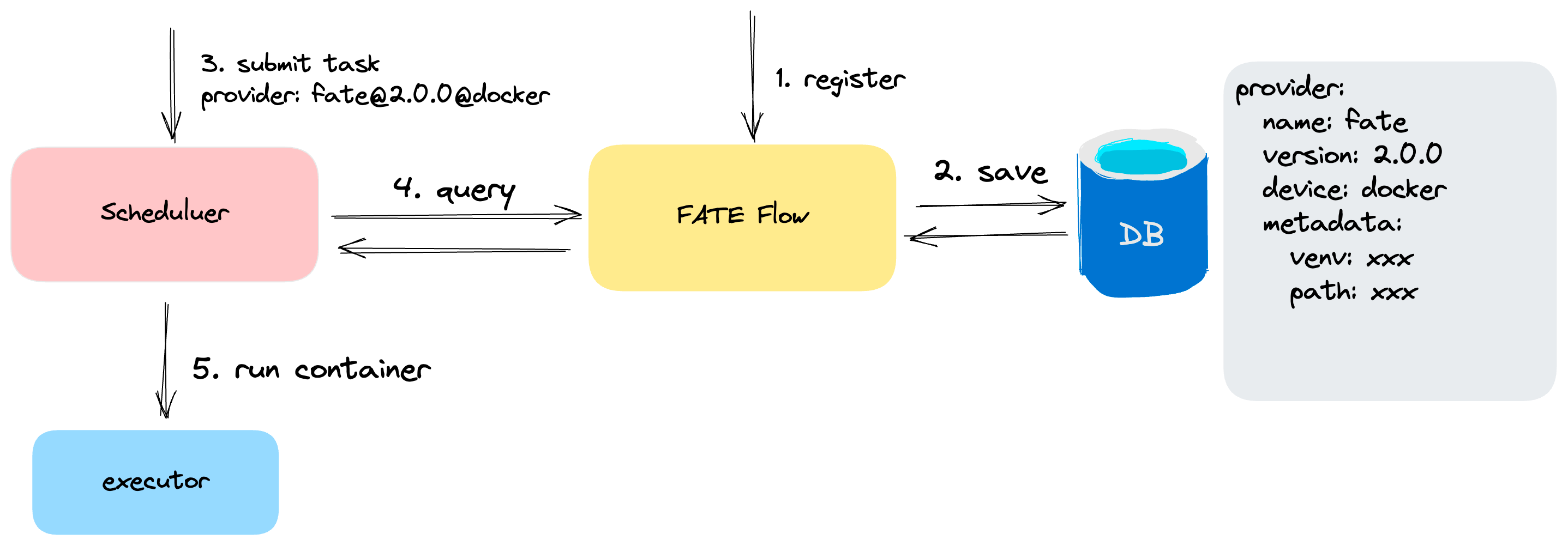
6. Task Component Center
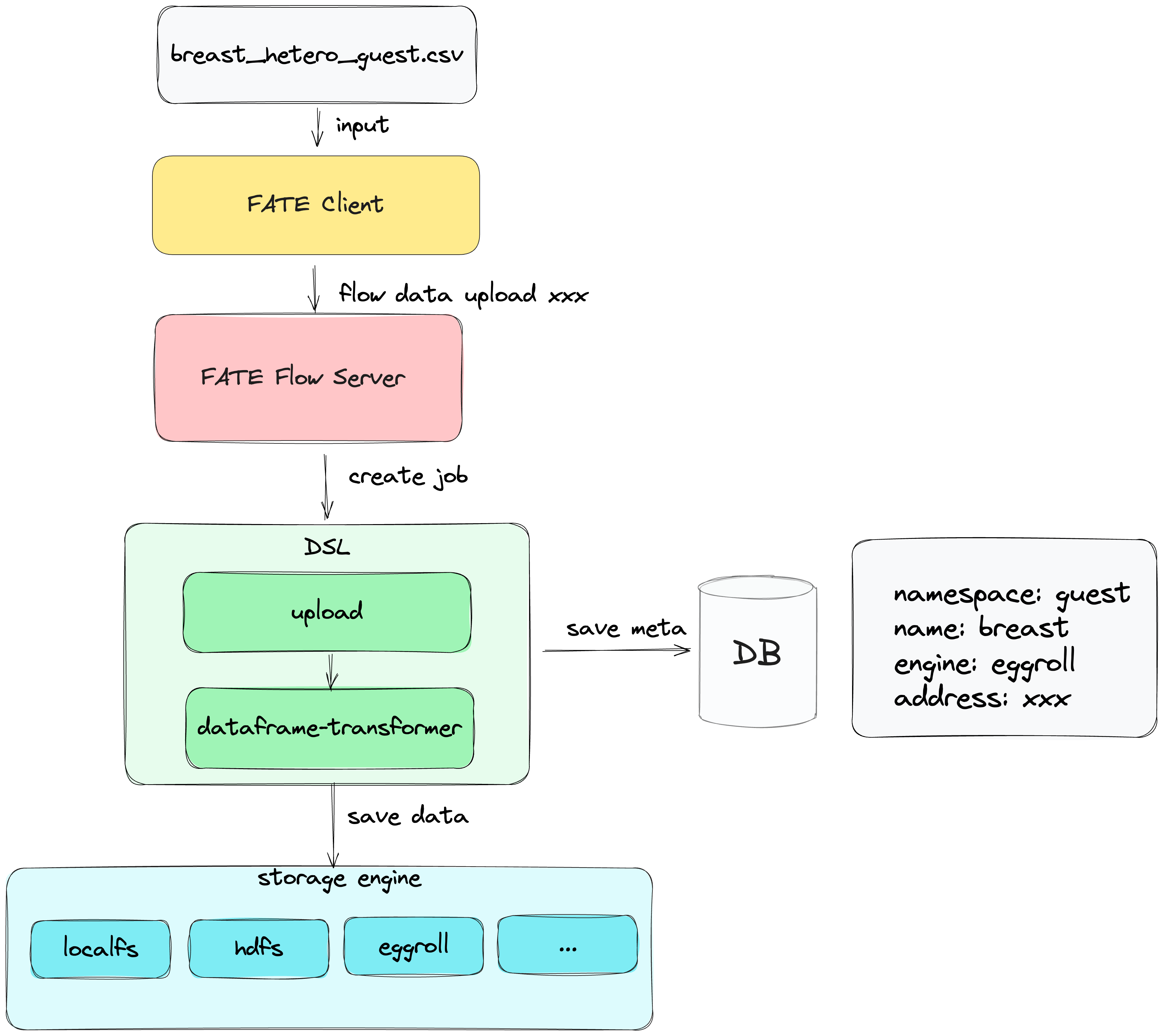
7. Data Access